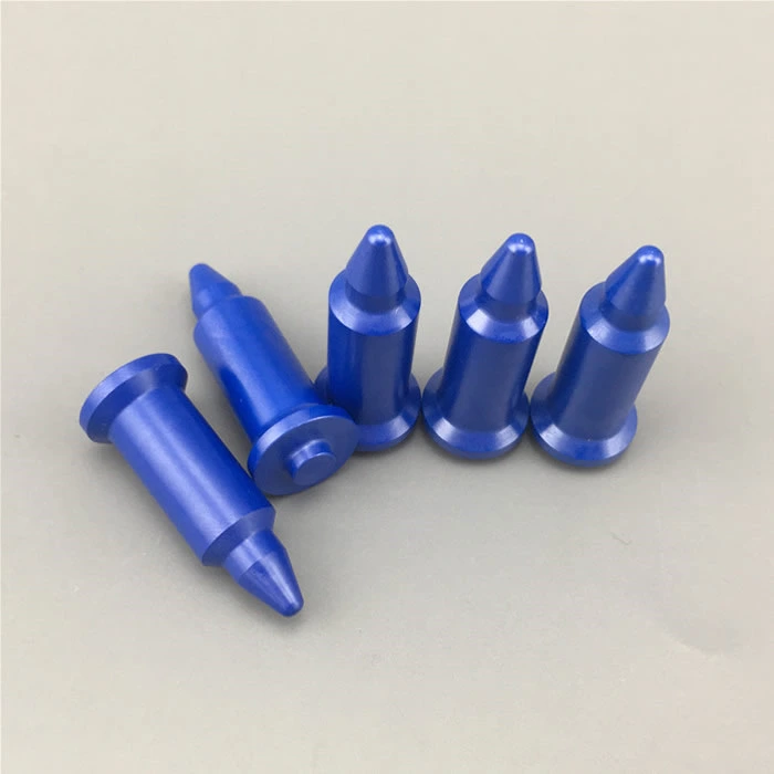
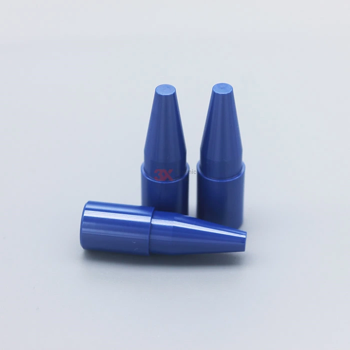
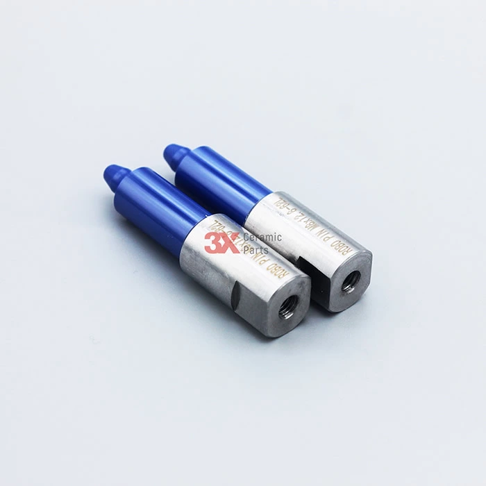
Ceramic Guide Pin
- Brand Name
- 3X Ceramic Parts
- Material Type
- Blue Zirconia , White Zirconia , Silicon Nitride , Alumina Ceramic
- MOQ
- 3 pcs each model
- Specification
- standard or customized
- Color
- blue , white , black
- Surface finish
- Normal or polished
- Application
- Welding Technology
- Main Property
- Long Service Life
3X Ceramic Parts Company provide different material of Ceramic Guide Pin:
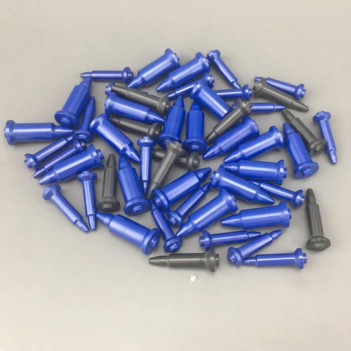
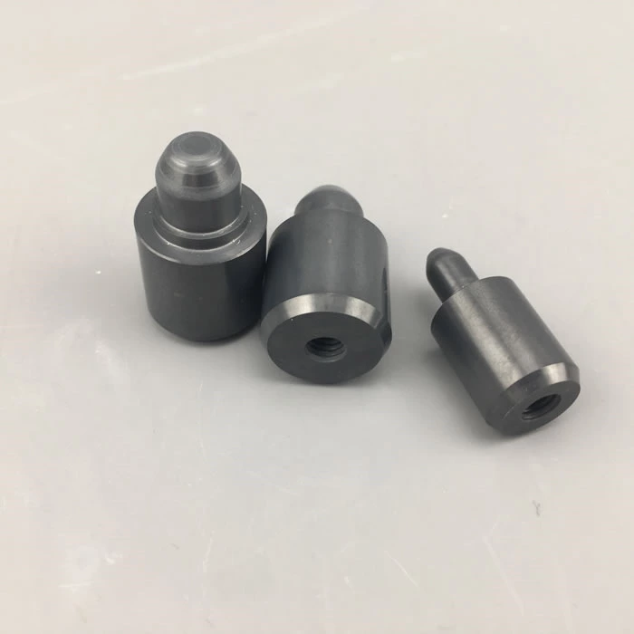
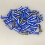
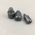
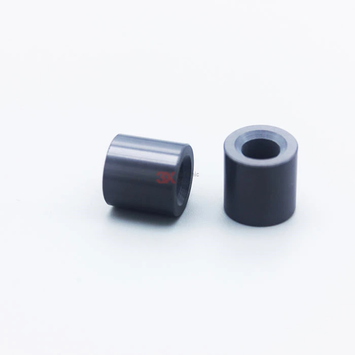
Silicone Nitride Guide Pin, Welding Pin
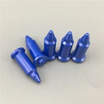
Nano Zirconia blue ceramic guide pin , raw material imported from Germany
China produced Blue Zirconia Ceramic material
ZTA material
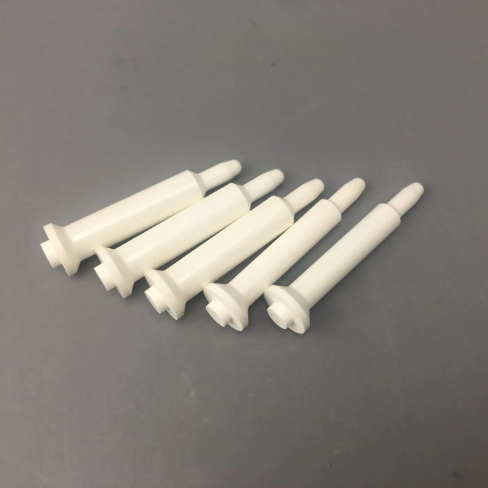
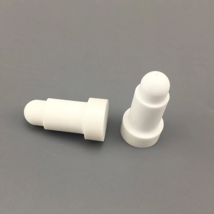
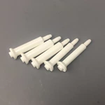
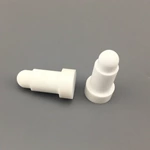
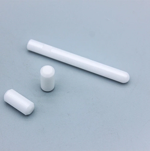
White Zirconia Ceramic material
Alumina Ceramic Material
Regular Dimension of Ceramic Guide Pin:
M4, M5, M6, M8, M10, M12, M14 Ceramic Cetering Pin
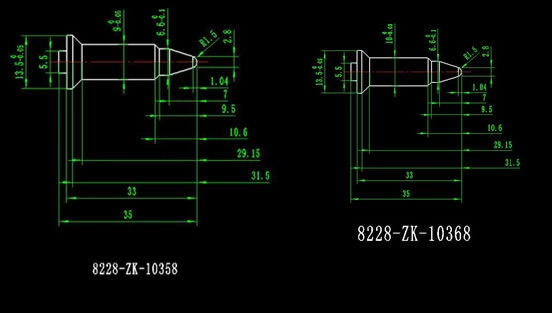
Nano Blue Zirconia Ceramic Guide / Welding Pin Properties :
Blue 3Y-TZP products are made of nano zirconia material with very low sinter temperature (1350 ℃) to full density ( >6.01g/ cm3) , with fine and small crystal size , such 3Y-TZP ceramics have extremely high bending strength ( > 1200 Mpa ) and toughness (12MPam1/2 ), which is nearly twice than normal zirconia ;
Yttrium element distribute in crystal homogeneously, which make this nano 3Y-TZP can stable in hot and
Humidity environment for a long time to keep the mechanical property and unlike normal 3Y-TZP ceramic crack because of “ low temperature aging ”
Benefits of nano blue zirconia guide pin :
In order to meet the growing demand for welding processes, we deliberately introduced nano-blue zirconia raw materials imported from Germany in 2013, using advanced hot isostatic pressing and sintering (HIP) and CNC grinding, supplemented by diamond polishing. The nano-welding locating pin and the limit pin with high precision, high strength, high toughness, high wear resistance, high corrosion resistance and high temperature resistance are prepared, and the durability is 40 times of that of the steel. It is the pin of the Japanese KCF material. More than double.
The locating pin of the nano-zirconia material exhibits the advantages of ultra-high performance when directly contacting the welding material:
-Extremely high wear resistance, the wear is more than three times that of steel in the same environment; Good rigidity and good shape retention. During use, even if there is a large impact force, deformation will not occur;
- Never stick to slag. Due to the unique non-wetting properties of the nano-ceramics, the spattered slag will not stick to the pins during the welding process, and no cleaning or other treatment is required.
- non-conducting, electrically insulating, the voltage can reach millions of volts without breaking through the conduction;
- It can withstand extremely high working temperatures. It still shows excellent stability when the temperature reaches 1200 °C. More importantly, the material has very good thermal shock resistance, that is, the temperature is short during welding. It will rise to seven or eight hundred degrees or above, or it will naturally cool in the air after welding, and the material will not break.
At the same time, in order to facilitate the service to customers, I offer a large number of standard solutions, including:
- welding centering pin;
- limit pin;
- positioning pin;
- electrode assembly;
- bolt head insulation sleeve;
- welding fixture assembly;
- MIG/MAG welding protection nozzle.
For different welding equipment, we also offer different solutions:
- Provide a shorter type of centering pin for manual feed mode;
- Provide a longer type of centering pin for automatic feed mode;
- Provides a long neck-type centering pin for the special construction of the hat nut;
- Provide welding pins for customer non-standard equipment, which can be customized according to drawings and samples.
Ceramic Guide /Welding Pin Different Material Comparison Datasheet :
| Material Comparison Datesheet | ||||||
| Material Property | Unit | 99.7% Alumina | ZTA | ZrO2 ( Y-PSZ ) | ZrO2 NANO ( 3Y- PSZ) | Si3N4 |
| Color | ivory | white | White | Blue | grey | |
| Density | g/cm | 3.9 | 4.1 | 6.0 | 6.0 | 3.2 |
| Bending Strength | MPa | 390 | 600 | 1300 | 1300 | 750 |
| Compressive Strength | MPa | 3900 | 3600 | 3000 | 3000 | 2500 |
| E-Modulus | GPa | 390 | 350 | 205 | 205 | 320 |
| Impact Strength | MPa m1/2 | 5.2 | 7.5 | 12 | 12 | 6.7 |
| Weibull Modulus | 12 | 18 | 25 | 25 | 15 | |
| Vickers Hardness | HV0.5 | 2000 | 1600 | 1150 | 1150 | 1650 |
| Thermal Expansion | 10-6 K-1 | 5.5-8.4 | 6.0-8.6 | 10 | 10 | 3.4 |
| Thermal Conductivity | W/mK | 28 | 18 | <2 | <2 | 22 |
| Thermal Shock Resistance | — T℃ | 280 | 320 | 280 | 280 | 550 |
| Max.Operating Temperature | ℃ | 1700 | 1000 | 1000 | 1000 | 1000 |
| Specific Resistance at 20℃ | cm | > 1015 | >1015 | >1010 | >1010 | >1011 |
| Dielectric Strength | KV/mm | 30 | 20 | |||
| M4,M5,M6, M8, M10, M12 Silicon Nitride Guide Pin standard size | |||||||||
| Drawings | Material | Model | Specification | ||||||
| D | d | L | R | r | E | ||||
| Silicon Nitride | 3X-SN1-M4 | 12 | 4.8 | 6.5 | 11.5 | 1 | 6.24 | ||
| 3X-SN1-M5 | 5.8 | 8.5 | 15.75 | 1 | 5.37 | ||||
| 3X-SN1-M6 | 6.8 | 11 | 24.7 | 1.5 | 4.5 | ||||
| 3X-SN1-M8 | 8.8 | 12.5 | 22.31 | 1.5 | 2.77 | ||||
| 3X-SN1-M10 | 16 | 10.8 | 14 | 28.86 | 2 | 4.5 | |||
| 3X-SN1-M12 | 12.8 | 17 | 27.77 | 2 | 2.77 | ||||
| Drawings | Material | Model | Specification | Remark | |||||
| D | d | d1 | R | L | I | E | |||
| Silicon Nitride | 3X-SN2-M4 | 12 | 4.8 | 3 | 1.5 | 5.5 | 2 | 6.24 | |
| 3X-SN2-M5 | 5.8 | 4 | 2 | 2 | 1.5 | 5.37 | |||
| 3X-SN2-M6 | 6.8 | 4.8 | 2.4 | 2.4 | 1.5 | 4.5 | |||
| 3X-SN2-M8 | 8.8 | 6.5 | 3.25 | 3.25 | 2 | 2.77 | |||
| 3X-SN2-M10 | 16 | 10.8 | 8.6 | 4.3 | 4.3 | 2 | 4.5 | ||
| 3X-SN2-M12 | 12.8 | 10.6 | 5.3 | 5.3 | 4 | 2.77 | |||
| Drawings | Material | Model | Specification | ||||||
| D | d | d1 | L | I | R | r | |||
| Silicon Nitride | 3X-SN3-M4 | 12 | 4.8 | 3 | 9 | 2 | 16.25 | 1 | |
| 3X-SN3-M5 | 5.8 | 4 | 9 | 1.5 | 15.58 | 1.5 | |||
| 3X-SN3-M6 | 6.8 | 4.8 | 11 | 1.5 | 51.83 | 1.5 | |||
| 3X-SN3-M8 | 8.8 | 6.5 | 12.7 | 2 | 16.95 | 1.5 | |||
| 3X-SN3-M10 | 16 | 10.8 | 8.6 | 14 | 2 | 16.12 | 2 | ||
| 3X-SN3-M12 | 12.8 | 10.6 | 17 | 4 | 11.3 | 3 | |||
| Drawings | Material | Model | Specification | ||||||
| L1 | L2 | L3 | D1 | D2 | D3 | R | |||
| Silicon Nitride | 3X-SN4-M5 | 19.5 | 5 | 4 | 10 | 5.7±0.1 | 4±0.1 | 2 | |
| 3X-SN4-M6 | 22 | 5 | 5.2 | 10.5 | 6.8±0.1 | 4.9±0.1 | 2.5 | ||
| 3X-SN4-M8 | 24 | 5 | 5.2 | 11.5 | 8.6±0.1 | 6.7±0.1 | 3.4 | ||
| 3X-SN4-M10 | 25 | 5 | 5.5 | 13.5 | 10.3±0.1 | 8.5±0.1 | 4.3 | ||


